Overview of Data Center Facility
A typical data center facility will consist of components as depicted in below picture. Data center room is where IT racks are located. Electrical room provides switch boards for the facility and connect from the outside utility or genset to the whole facility. UPS room and battery room are to put UPS and batteries. Mechanical room is where chillers and pumps are located to support the cooling system in the data center. Chiller is connected to the cooling tower or outdoor heat rejection unit which is located outside or at the roof top of the building. Network Operation Center (NOC) is where people monitor the performances like in NASA facility. Customer can use Staging Area to prepare equipment and do some configuration, before installed at the racks inside data center room.
A typical data center facility will consist of components as depicted in below picture. Data center room is where IT racks are located. Electrical room provides switch boards for the facility and connect from the outside utility or genset to the whole facility. UPS room and battery room are to put UPS and batteries. Mechanical room is where chillers and pumps are located to support the cooling system in the data center. Chiller is connected to the cooling tower or outdoor heat rejection unit which is located outside or at the roof top of the building. Network Operation Center (NOC) is where people monitor the performances like in NASA facility. Customer can use Staging Area to prepare equipment and do some configuration, before installed at the racks inside data center room.

Data Center Floor Plan
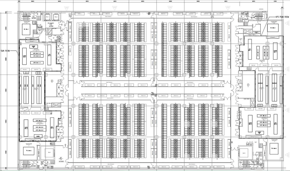
Below is one example of floor plan for Tier-3 Data Center. It split into two symmetrical area, with each area (left or right) is taken power separately. In general data center area is divided into:
- IT racks which occupy most of the area in the middle.
- UPS room. Tier-3 requires concurrent maintainable configuration so there should have redundant UPS's in place (one active, one standby).
- Battery room. It is normally separated from UPS and electrical rooms.
- MDF room. This is cross-connect for backbone network cabling.
- Transformer room.
- Fire fighting & smoke stop lobby.
- CRAH. CRAH units are usually installed at each end of along side row of racks. The units are installed outside IT room so the maintenance subcontractor can perform the service work without touching any IT equipment.
- PDU. This is where 3-phase electrical wiring is arranged into 3 separate sets of 1-phase wiring.
Electrical Diagram
Below is one example of electrical diagram which depicts main equipment used in the facility. This is to support 1.2MW load. We will touch each equipment later on.

Data Cabling Design
10GBase-T will become the standard for high speed data transfer in most internet data centers so we need to design cabling using twisted pair copper cabling with cat 6A, which can span to 100m length. 10GBase-T can use RJ-45 connectors so there is no change in the way to connect to network equipment. It is able to auto-negotiate line rate to provides migration path from 1 Gb/s to 10 Gb/s Ethernet. SAN on fibre channel may use multimode fiber optic cabling to provide low latency, low power consumption and longer distance (upto 300m).
In term of cabling data center zoning is divided into ER, MDA, HBA, ZDA (optional), and EBA, which are depicted in below picture.

Modularity in cabling is using patch panel. Below pictures show the patch panel & the end point of the equipment.
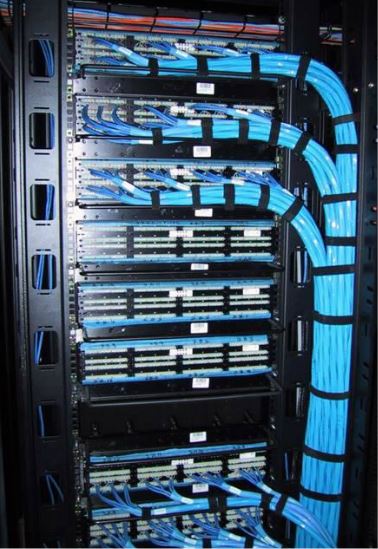
|
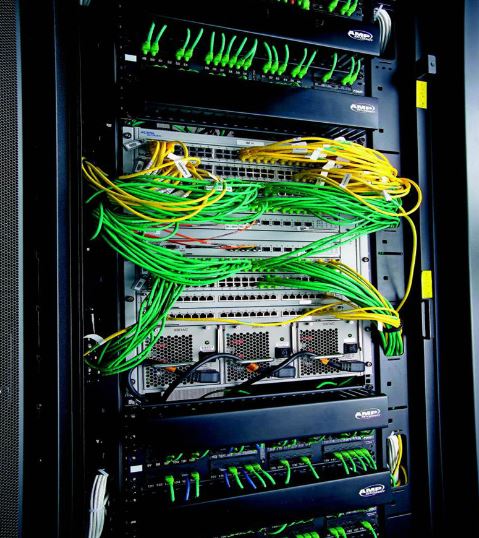
|
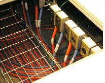
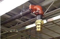
Overhead and under-raised-floor deployment of cabling are shown in below pictures. Do not overbend the cable and overtighten the rope as it will affect the cabling performance.
|
Overhead Deployment
Middle layer – fiber Top layer – power 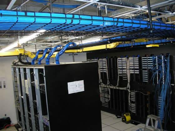
|
Under-raised-floor Deployment

|
Power Cabling Design
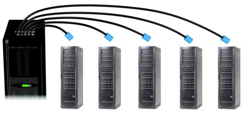
There are several ways to distribute power from PDU to each rack, either through overhead or under-floor deployment.
There are several ways to distribute power from PDU to each rack, either through overhead or under-floor deployment.
- Panel Board Distribution. The contractor will connect each individual branch circuit to each IT rack. This low cost method is suitable for upto 75kVA.

- PDU. It is factory-configured with pre-installed breaker. Power cable assemblies (whip) are also provided from PDU to IT rack.
|

|
- Modular Power Distribution System. Each branch circuit will be wired either through overhead or underfloor power busbar. At the rack point it has bus plug-in units to connect cable to the rack.

Precision Cooling
Heat in data center is primarily sensible heat. Cooling in data center runs 7x24 hours. We need to deploy precision aircond that has over 80% sensible heat ratio and is designed for continuous operation. For data center we follow ASHRAE TC9.9 (2011) Class A1 for tighly controlled environment, with the recommended operating temperature between 18-27degC and humidity between 35-50%. Please refer to below psychrometric chart under A1 area.

Any cooling system will follow basic refrigeration cycle as shown below.

Most big data centers in ASEAN implement chillers. Chillers are where the heat exhange take place. The chilled water will enter CRAH. With the help of fans the returned hot air will pass through the cooling coils in CRAH and release heat to the water. The cold air from CRAH will travel through the plenum (for raised floor system) and come out from the perforated tiles, then go through the perforated door of the rack to then cool the IT equipment.
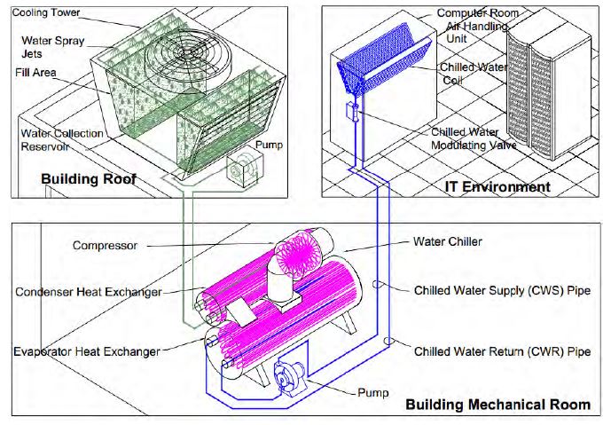
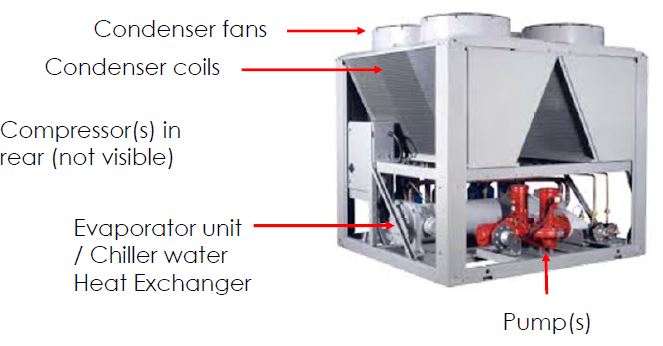
The warm water from the chiller will return to chiller and go through heat exchange process in the evaporator, and removal of refrigerant vapour from the compresor. There are two types of chiller: water-cooled chiller and air-cooled chiller. In water-cooled chiller we need mechanical room for chiller and pump, as shown below. While in air-cooled chiller all components are situated outdoor (see picture below).
The warm water from the chiller will return to chiller and go through heat exchange process in the evaporator, and removal of refrigerant vapour from the compresor. There are two types of chiller: water-cooled chiller and air-cooled chiller. In water-cooled chiller we need mechanical room for chiller and pump, as shown below. While in air-cooled chiller all components are situated outdoor (see picture below).
|
Water-cooled Chiller
|
Air-cooled Chiller
|
We recommend chiller with coefficient of performance (COP) of between 3.5 to 5.0 or above. For 1.2MW data center, typically you need about 1.3MW sensible heat cooling. Chiller with COP 5.0 will only require total input power of 0.26MW. That will lower PUE of the data center to 1.22.
Each CRAH manufacture publish the data of sensible heat removal capacity of each CRAH model, which is based on certain assumptions like water temp entering from chiller to CRAH, temperature rise of return water, the temp & humidity of the return air to CRAH. Once we get the CRAH capacity, we can calculate how many units of CRAH needed to provide sufficient cooling for the data center. For higher tier data center, we need to add more CRAH for redundancy and concurrent maintenance.
Each chiller has its own heat removal capacity and need to size accordingly with CRAH unit.
Cooling Distribution Systems
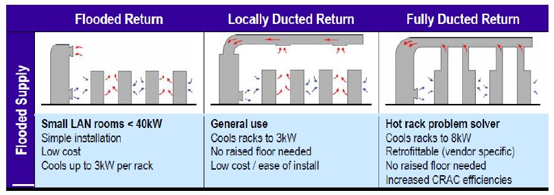
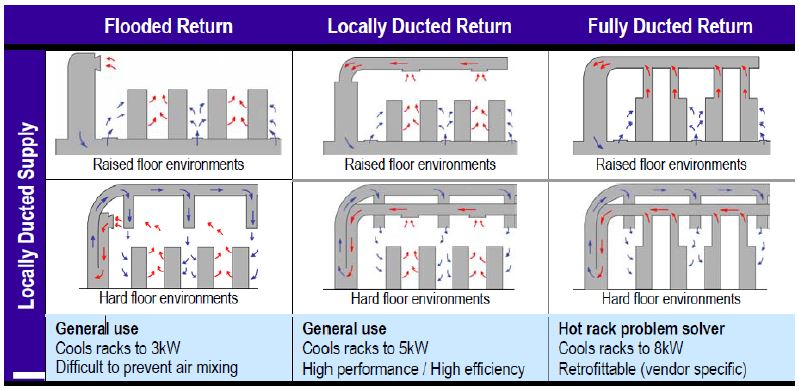
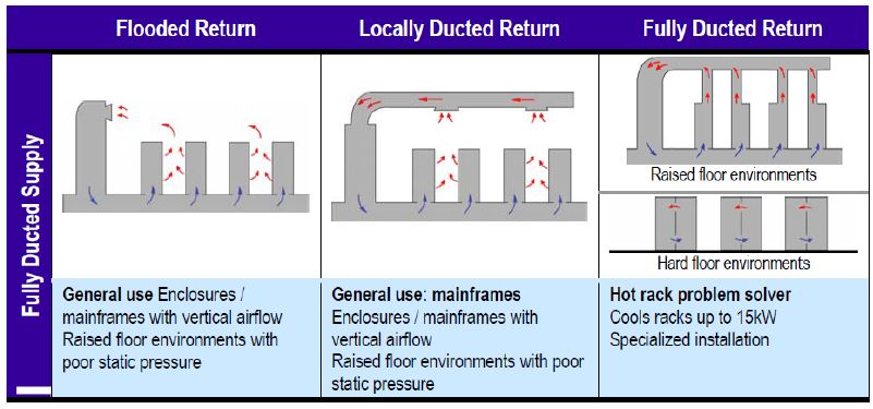
Every cooling distribution system has a supply system and a return system. The supply system distributes the cool air from the CRAC unit to the load, and the return system takes the exhaust air from the loads back to the CRAC. For both the supply and the return, there are three basic methods used to convey air between the
CRAC and the load: Flooded, Locally Ducted, Fully Ducted. So there are 9 possible combinations of cooling distribution system for both raised floor & hard floor facility, as shown at below picture.
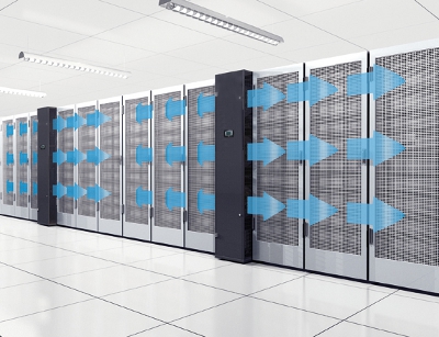
Air Containment Strategies
Basically there are 3 methods of air containment in data center:
1. Hot Aisle Cold Aisle without any containment

|
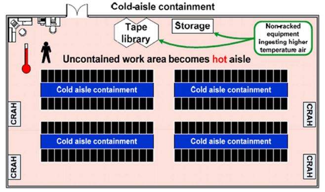
2. Cold Aisle Containment System
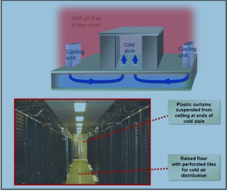
|
The containment encloses cold air come out from the perforated tiles of the raised floor
|
|
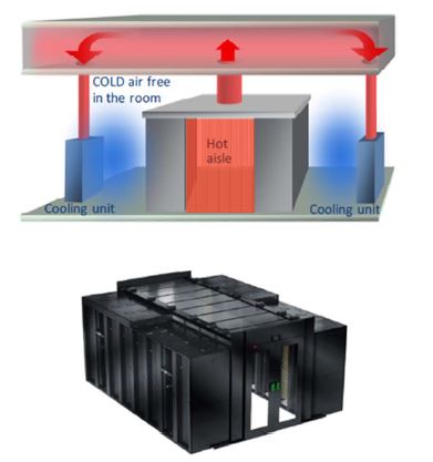
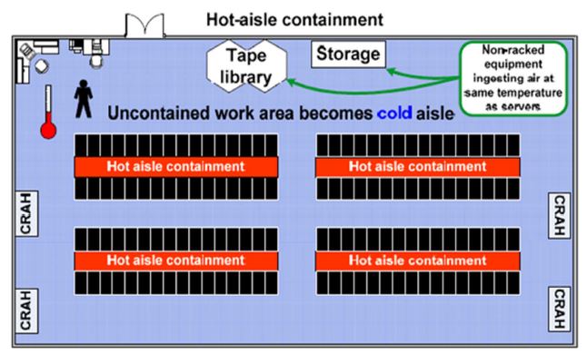
3. Hot Aisle Containment System
|
Containment encloses the hot exhaust air from IT rack
|
Under practical work environment temperature constraints and temperate climates, hot-aisle containment provides significantly more economize mode hours and lower PUE compared to cold-aisle containment. This is true regardless of the type of cooling unit or heat rejection method used.
Emerson Network Power and Panduit are among the strong proponent of cold aisle containment system, while APC (Schneider Electric ITB) is the strong advocate of hot aisle containment system. All can supply any type of containment.
Emerson Network Power and Panduit are among the strong proponent of cold aisle containment system, while APC (Schneider Electric ITB) is the strong advocate of hot aisle containment system. All can supply any type of containment.
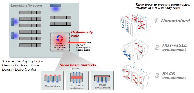
High Density Pod
Allows rapid deployment of high-density racks within a traditional low density data center. Support a mixed-density data center environment for a fraction of the cost of building an entirely new data center.
Allows rapid deployment of high-density racks within a traditional low density data center. Support a mixed-density data center environment for a fraction of the cost of building an entirely new data center.
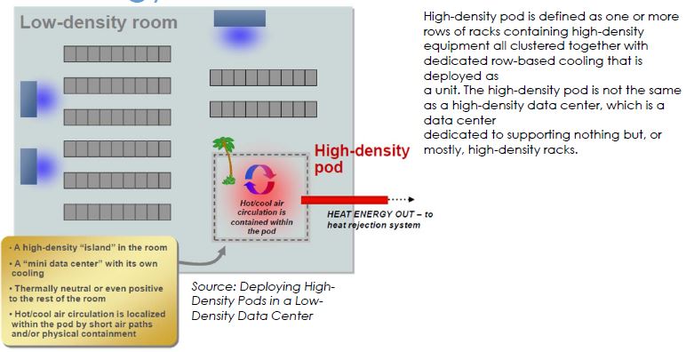
There are 3 methods to high density pods in a low density data center, as depicted in below picture.
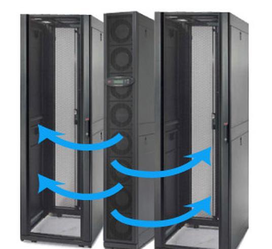
In-row Cooling
When IT racks designated for the pod are moved and relocated frequently and when IT racks are used from a variety of different vendors, we need row-based air conditioner. There is distance limitation between air cond and IT racks so we may need to install extra in-row air cond for the racks located toward at the end of the row. APC is the proponent of In-row cooling. Stulz is also selling in-row cooling.
When IT racks designated for the pod are moved and relocated frequently and when IT racks are used from a variety of different vendors, we need row-based air conditioner. There is distance limitation between air cond and IT racks so we may need to install extra in-row air cond for the racks located toward at the end of the row. APC is the proponent of In-row cooling. Stulz is also selling in-row cooling.
|
|
UPS System Design Configuration
Data centers usually use double conversion online UPS for 10kVA to 1.6MVA, while for below 3kVA on rack level we may use line interactive 1-phase rackmount UPS. Battery backup time could be designed from 10 minutes to several hours, depending on the utility power quality and the availability of genset. For 15-min backup batteries alone could cost about 30% of UPS system. Adequate space & ventilation is also required to batteries. With such expensive capex on batteries, my advice is use batteries as minimal as possible and activate standby genset for any prolonged blackout. Don't use batteries as the substitute for standby genset, unless your data center is truly designed with energy storage system from solar or wind.
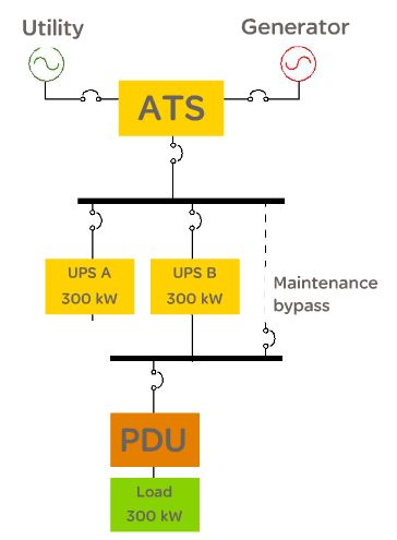
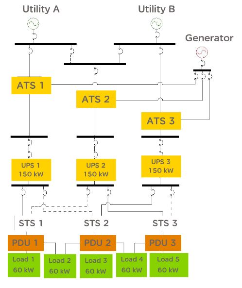
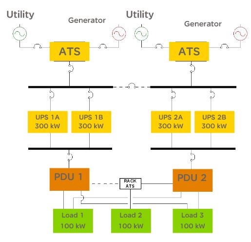
Data center will select UPS design configuration based on the targeted tier-level of the data center that they want to achieve. There are several UPS design configuration, which are shown in below pictures:
1. Capacity - N
2. Isolated redundancy
3. Parallel redundancy - N+1
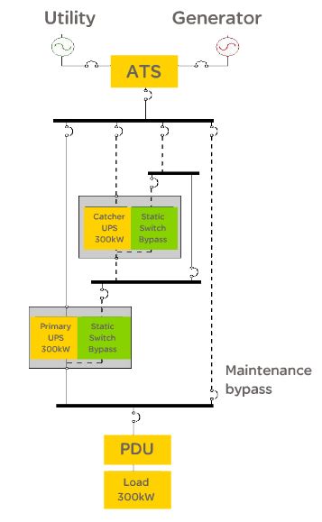
4. Distributed redundancy
5. System plus system redundancy - 2N
|
Isolated Redundancy
|
Parallel Redundancy (N+1)
|
|
Distributed Redundancy
|
Fault Tolerant Redundancy - 2N
|
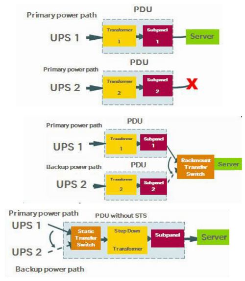
For dual power path environment, we need to install rackmount transfer switch as show below.
|
Rackmount Automatic Transfer Swicth
(2 input power cords with one preferred source) 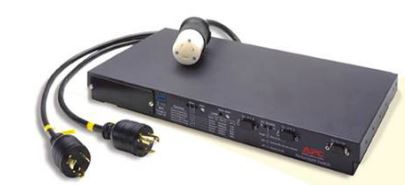
|
Single-cord Load connected to Dual Power Path
|
Fire Protection
Prevention, detection, communication and supression are components of fire protection.
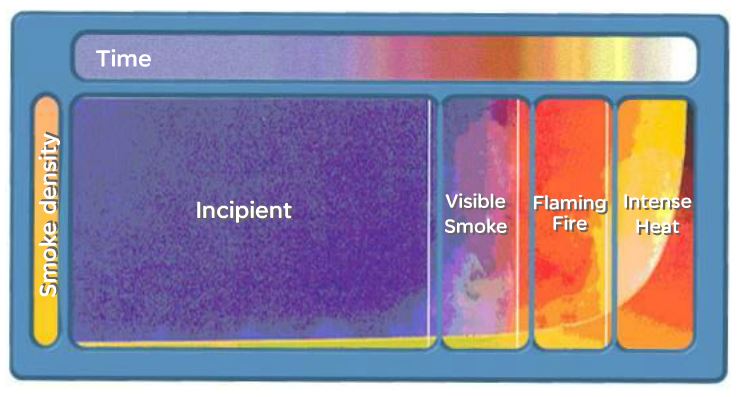
Three elements of fire and stages of combustion are explain in below pictures.
Prevention, detection, communication and supression are components of fire protection.
Three elements of fire and stages of combustion are explain in below pictures.
|
Three elements of Fire

|
Stages of Combustion
|
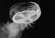
Smoke Detectors
Smoke detector can detect smoke at incipient stage and can be installed at the ceiling, above dropdown ceiling, below raised floors, or air handling ducts. Below are some pictures of smoke detectors.
Smoke detector can detect smoke at incipient stage and can be installed at the ceiling, above dropdown ceiling, below raised floors, or air handling ducts. Below are some pictures of smoke detectors.
|
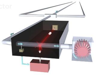
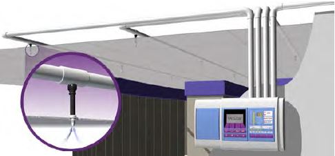
Very Early Smoke Detection Apparatus (VESDA)
|
Ionization Detector
Photoelectric Detector

|
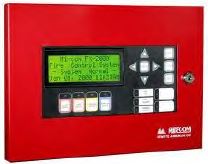
Fire Communication System
Fire communication system is mandatory for human safety in the event of fire. It is governed under NFP70 & SCDF. It consists of main control panel, fire alarm, abort station, horn strobes/alarm bells, strobe lights.
|
Components of Fire Communication System
Main Control Panel
|


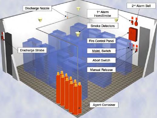
Fire Suppression
- Clean Agent
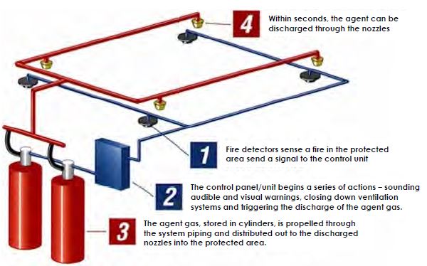
|
|

2. Inert Gas
Inert gas is to lower oxigen concentration. It can use Inergen (mixture of Nitrogen, Argon, CO2) or Argonite (Nitrogen, Argon). The gas is not hamrful to human. It must be stored in very high pressure tank and usually kept in separate room outside data center room. Inert gas requires more space to keep than clean agent. Inert gas is cheaper & easy to replace but requires more space.
3. Pre-action Sprinkler.
Unlike wet and drip pipe sprinkler, pre-action sprinkler doesn't hold water in the pipe in order to reduce water leak which can damage IT equipment. National Code from SCDF requires sprinkler in the building. A valve within the system is located outside the data center and keeps water from entering. In order for water to get past the valve, two events have to occur. First, a smoke detector has to let the system know that a fire is occurring; at that point, water moves into the pipes. However, the fire has to grow to a certain temperature before the valve will open and water can discharge into the room. Given that these two events have to occur before water will flow through the pipes that are located within the data center, the risk of an accidental leak is greatly reduced.
Sprinkler is considered as last resort in case all other means of fire suppression doesn't work. Data center people should know that after sprinkler action all IT equipment will be considered damage & data center is practically gone case.
4. Water Mist Suppression System
It discharges very fine water droplets. It removes oxigen and heat. It consumes less water and less space to store water.
ITIL for Data Center Physical Infrastructure
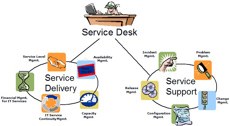
IT Infrastructure Library (ITIL) based on ISO20000 has been implemented in organizations for their IT operation relating to servers, storage, networking, etc. In some degree ITIL can be implemented in physical infrastructure relating to critical power, cooling, cabling, rack and security, fire protection. ITIL is divided into two parts: Service Delivery and Service Support. Service support consists of Incident Management, Problem Management, Change Management, Configuration Management, Release Management. While Service Delivery consists of Availability Management, Capacity Management, Service Level Management, IT Service Continuity Management, and Financial Management. Both will be managed under Service Desk.
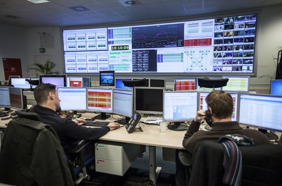
There are several tools available to automate the processes. For e.g. Remedy or RT is used for Service Desk. Nagios is used for Availability Management. MRTG is used for Service Level Management. Rancid is used for Change Management. Netdot is used for Configuration Management (including Cable Plant). These tools are monitored in the Network Operation Center (NOC).
|
ITIL Framework
|
NOC
|
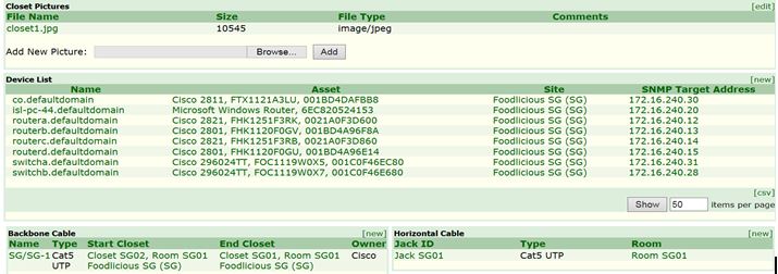
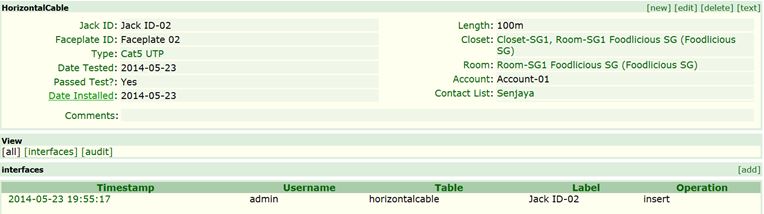
Below shows the screenshot of Netdot which is CMDB to store information on devices, assets, VLANs, address space, DNS records, DNS zones, DHCP, contact and cable plant.
|
Cable Plant in Netdot

List of Devices in the Closet
|
Details of the Closet

Horizontal Cable
Backbone Cable

|
Implementing OSHA Logout Tagout (LOTO)
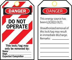
Lockout-tagout (LOTO) is a safety procedure which is used to ensure that equipment or machines are properly shut off and not started up again prior to the completion of maintenance or servicing work. It requires that hazardous power sources be "isolated and rendered inoperative" before any repair procedure is started. "Lock and tag" works in conjunction with a lock usually locking the device or the power source with the hasp, and placing it in such a position that no hazardous power sources can be turned on. The procedure requires that a tag be affixed to the locked device indicating that it should not be turned on.
The program requirement needs to include the followings:
- Written program
- Statement of intended use
- Classification of personnel
- Training of personnel
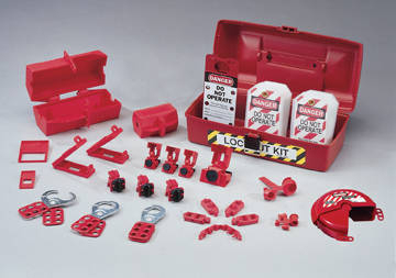
- Lockout tagout devices
- Enforcement of procedures
- Inspection of system
The program must clearly procedural steps in shutting down, isolating, blocking, and isolating. In data center facility the program will apply during the preventive and corrective maintenance services for all electrical, mechanical, chemical equipment.
Shutdown steps will involve the following sequences:
- Prepare and announce the shutdown
- Turn off equipment
- Isolate the energy source
- Apply lockout tagout devices
- Release all residual energy
- Verify isolation
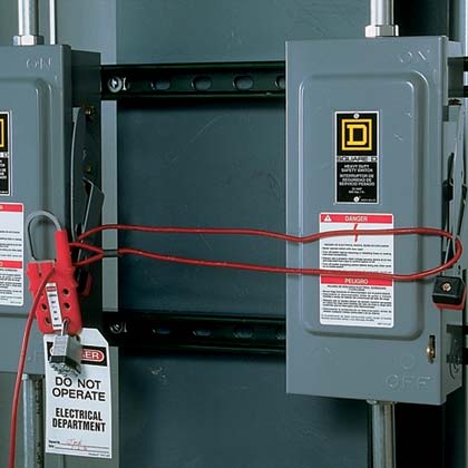
|
Single LOTO

|
|
Critical Work Packages
From time to time data center may conduct some projects, e.g. to build integrated energy management system to improve energy efficiency of power & cooling to reduce environmental performance. Data center project management requires the documentation of Critical Work Packages, which are defined by brief statements of Activity:
From time to time data center may conduct some projects, e.g. to build integrated energy management system to improve energy efficiency of power & cooling to reduce environmental performance. Data center project management requires the documentation of Critical Work Packages, which are defined by brief statements of Activity:
- Description
- Resources of skill and expertise
- Estimates of effort & duration
- Schedule
- Risks
- Budget
Critical Facility Management
There are several companies that specialize in the facility management. That way the owner of the data center will focus on the colocation and cloud business and IT management instead of worrying on the facility. The facility management company has its own personnel and also deploy subcontractors for certain services. The facility management company need to address and work together with the owner on below five (5) areas:
1. Service & Delivery
3. Value-added Innovations
5. Organizational Values & Policies
Standard Operating Procedure (SOP) is fixed operating procedure (functional or administrative) and can be referenced whenever needed.
Method of Procedure (MOP) the detailed, step-by-step procedure that is used when working on or around any piece of equipment that has the ability to directly or indirectly impact the critical load. A library of MOP‟s should exist for scheduled maintenance operations, and should be written for corrective maintenance and installation activities as well.
Emergency Operating Procedure (EOP) is an emergency response procedure for a potential or previously experienced failure mode. It covers how to get to a safe condition, restore redundancy and isolate the trouble.
Electronic Documentation Management System (EDMS) is used to provide electronic storage and retrieval of important facility documentation. This ensures that the material is organized, accessible, backed up and available for auditing. The EDMS contains workflow used for document review and approval by Quality Control.
Computerized Maintenance Management System (CMMS) tracks all work orders and helps in the scheduling, assignment and tracking of all the facility maintenance activities. The record of these activities can be used to generate vital statistics about facility health, program effectiveness and resource utilization.
There are several companies that specialize in the facility management. That way the owner of the data center will focus on the colocation and cloud business and IT management instead of worrying on the facility. The facility management company has its own personnel and also deploy subcontractors for certain services. The facility management company need to address and work together with the owner on below five (5) areas:
1. Service & Delivery
- Preparation (project kickoff, O&M program, staffing)
- Execution (evaluation of subcontractor performance, scope of works, team makeup)
- Measurement (KPI metrics, frequency of report)
- Personnel management (skill, assessment, turnover, replacement, career progression)
- Training (critical systems training, drill & scenario training, site-specific training, certification)
- Documentation (drawings, asset database, preventive maintenance scope of work, maintenance schedule, work rules, safety program, facility reports, walkthough checklist)
- Processes & Procedures (change control, maintenance programs, MOP, SOP, EOP, AP)
- Quality systems (QA, QC, QI plans, TQM, Six Sigma)
- Systems (CMMS/EDMS)
3. Value-added Innovations
- Cost management
- Energy efficiency
- Quality & Process improvements
5. Organizational Values & Policies
Standard Operating Procedure (SOP) is fixed operating procedure (functional or administrative) and can be referenced whenever needed.
Method of Procedure (MOP) the detailed, step-by-step procedure that is used when working on or around any piece of equipment that has the ability to directly or indirectly impact the critical load. A library of MOP‟s should exist for scheduled maintenance operations, and should be written for corrective maintenance and installation activities as well.
Emergency Operating Procedure (EOP) is an emergency response procedure for a potential or previously experienced failure mode. It covers how to get to a safe condition, restore redundancy and isolate the trouble.
Electronic Documentation Management System (EDMS) is used to provide electronic storage and retrieval of important facility documentation. This ensures that the material is organized, accessible, backed up and available for auditing. The EDMS contains workflow used for document review and approval by Quality Control.
Computerized Maintenance Management System (CMMS) tracks all work orders and helps in the scheduling, assignment and tracking of all the facility maintenance activities. The record of these activities can be used to generate vital statistics about facility health, program effectiveness and resource utilization.